Improving the reliability of BMS systems with transformers
The conversion of electric grids to renewable energies, especially wind power and photovoltaics, which are not always available, is fueling the need for larger energy storage systems.
These require a sophisticated battery management system (BMS) for reliable operation. BMS transformers can be used to insulate the components and improve the EMC properties.
Two key pillars of the energy transition are the widespread use of wind power and photovoltaic systems. In principle, wind and sunshine are free and inexhaustible, meaning that these forms of energy can be used to generate electricity in a climate-friendly way. Unfortunately, there is one drawback: both forms of energy are not continuously available and are subject to major fluctuations. Therefore, if you don't want the lights to go out when it's dark, you need either power plant capacity or buffer storage that can at least temporarily replace the energy missing from the power grid. A case study by the Federal Environment Agency and an article on the "energie-experten.org" portal provide an overview of the various methods of electrical energy storage. Figure 1 shows the most common methods for storing electrical energy in terms of storage duration and capacity.
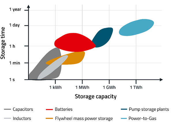
Figure 1: Method for storing electrical energy in terms of storage duration and capacity
Advances in battery technology are now making large battery systems increasingly attractive as buffer storage systems. These energy storage systems then have the task of balancing out the fluctuating energy supply and changing energy demand as well as cushioning feed-in and consumption peaks.
If the company Kyon Energy, which specializes in storage technologies for the energy transition, has its way, the storage capacity for large battery storage systems in Germany will increase by a factor of 40 to 57 GWh with a total capacity of 15 GW by 2030. This is the conclusion of a study commissioned by the company together with BayWa, Eco Stor, enspired and Fluence Energy from the consultancy firm Frontier Economics [3]. The study also assumes that large-scale battery storage systems can generate €12 billion in economic added value by 2050 by shifting the availability of electricity from times of surplus to times of shortage. At the same time, the study shows that large-scale battery storage systems have a price-reducing effect on wholesale prices and reduce the wholesale price by an average of around €1/MWh between 2030 and 2050. If there is no possibility of using stationary battery storage instead of additional gas-fired power plants, the wholesale price could be expected to increase €4/MWh on average between 2030 and 2050.
Which types of battery storage systems do exist?
The energy storage systems considered here typically work with electrochemical battery cells. There are various electrochemical battery cells that differ in their respective properties and areas of application. One prominent example is the widely used lithium-ion battery cells. Depending on the area of application, these systems can be differentiated according to their capacity and performance. The physical mode of operation is identical. Although there is no direct correlation between capacity and maximum charging or discharging power, it can often be assumed in practice that the greater the capacity of a battery, the greater its maximum charging or discharging power can be.
First, it makes sense to divide batteries into three size ranges:
- Energy storage for households and small businesses, 3 to 20 kWh
- Energy storage for communities and businesses, 20 to 100 kWh
- Energy storage for electricity grid operators 100 kWh to 5 MWh
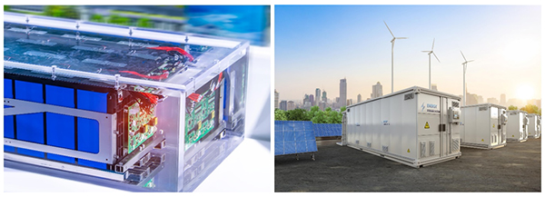
Figure 2: The range of energy storage systems extends from small battery systems (3 to 20 kWh, left) for households to large ones (100 kWh to 5 MWh, right) for grid operators
How is a battery storage system constructed?
A battery storage system essentially consists of a battery pack with individual battery cells in which reversible electrochemical processes take place for charging and discharging. However, due to various influences such as manufacturing tolerances, ageing, etc., the individual battery cells generally do not behave exactly uniformly but are characterized by deviations in charging and discharging behavior and the state of charge.
This is where the battery management system (BMS) comes into play, which is designed to compensate for these differences in the charging behavior and state of charge of the individual battery cells in such a way that reliable and safe operation of the battery is guaranteed. For this purpose, the BMS has a charging and monitoring unit that monitors the current, voltage and temperature of the individual battery cells and is controlled by a BMS controller (Fig. 3). The BMS controller in turn communicates with higher-level control units via bus systems and controls the power flow to and from the battery. The BMS is basically the brain of the battery. The state of charge (SOC), the state of health (SOH) and the remaining capacity are three important metrics that are tracked and calculated by the BMS. It makes decisions based on the information it collects that affect the performance and longevity of the battery. The BMS actively protects the battery from risks such as deep discharge, overcharging and overheating.
Typical functions of a BMS:
- Protecting the battery from operating outside its safe operating range
- Monitoring the state of charge and health of the battery
- Calculation and reporting of secondary data
- Control of its environment
- Authentication and/or balancing of the battery cells
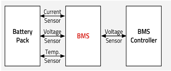
Figure 3: Structure of a battery management system. The BMS block in the center monitors the battery cells and controls charging and discharging processes
Which role do BMS transformers play?
The individual battery cells of a battery pack are connected in series, as are the downstream BMS controllers. Voltage differences and electromagnetic interference can occur between the components or circuit boards connected in series. Transformers can be used to isolate the components between the high-voltage and low-voltage sides and suppress EMI interference. This is particularly important to ensure that no dangerous voltages are transmitted to touchable parts or the BMS. The WE-BMS transformers fulfill this function and provide BMS insulation and EMI interference suppression for safe and reliable operation. Figure 4 shows the use of WE-BMS transformers in a battery management system.
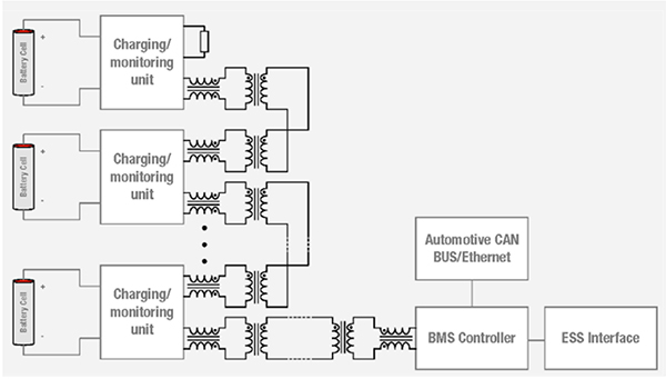
Figure 4: The WE-BMS transformers from Würth Elektronik provide galvanic isolation of the BMS and common mode chokes suppress EMI interference
What characterizes the WE-BMS transformers?
The WE-BMS transformers from Würth Elektronik are designed for high robustness and reliability. They have reinforced insulation in accordance with IEC 60664-1 and IEC 62368-1. These standards define safety requirements for transformers and for audio/video, information and communication technology equipment. With regard to electrical energy, requirements for high-voltage tests, insulation resistances and creepage and clearance distances are described, among other things. They are equipped with a triple-insulated wire on the primary and secondary sides for the highest operating voltage. To ensure the longevity of the insulation, the WE-BMS transformers are subjected to a partial discharge test in accordance with IEC 60664-1.
The operating voltage of the latest addition to the WE-BMS transformer range has been increased from 1000 to 1500 VDC. The test voltage was also increased from 4300 to 6400 VDC. The transformers are specified for an operating temperature of -40 to +125 °C and are UL-certified in accordance with the UL standard UL 62368-1 in document E507007.
Insulation, creepage and clearance distances
Important aspects in the design of a BMS transformer according to IEC 62368-1 are the creepage and clearance distances as well as the selection of suitable insulation for the wire. A distinction is made between functional, basic, supplementary and reinforced insulation. The differences in insulation can be seen in Figure 5.
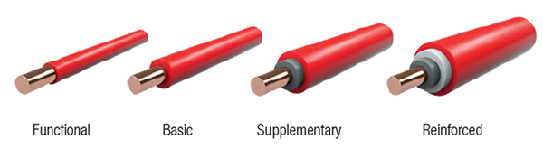
Figure 5: A distinction is made between functional, basic, supplementary and reinforced wire insulation
Functional insulation is the minimal level required for functionality. However, this type of insulation does not prevent electric shock. Basic insulation provides the user with simple protection against electric shock. The supplementary insulation goes beyond the basic insulation and provides further protection. Reinforced insulation provides an additional layer that works in a similar way to supplementary insulation. Even if the basic insulation fails, the supplementary insulation remains effective and protects the user.
The clearance distance is the shortest distance between two conductors through air. It is important to ensure sufficient clearance distances in order to protect people and systems from the effects of electrical operating voltages. The required clearance is determined by determining the overvoltage category, the degree of contamination and the operating voltage. The minimum clearance distance can then be determined using Table 14 of the above standard.
The creepage distance is the shortest distance along the surface of an insulating material between two conductive parts. The creepage distance is determined in a similar way to the clearance distance but includes the material’s comparative tracking index (CTI). By determining the overvoltage category, the degree of contamination and the working voltage, the minimum creepage distance can be calculated using Table 17 of the standard.
The difference between clearances and creepage distances is illustrated in Figure 6.
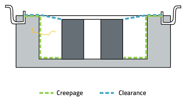
Figure 6: Creepage and clearance distances in the BMS transformer
In summary these specialized transformers from Würth Elektronik improve the safety and reliability of battery management systems.
Conclusion
BMS transformers are crucial for enhancing the reliability and safety of battery management systems in energy storage. As renewable energy sources grow, these transformers address key issues like insulation and EMI interference suppression, ensuring safe and efficient operation. The WE-BMS transformers from Würth Elektronik meet stringent standards and improve system durability, supporting a stable and sustainable energy supply. This advancement is vital for the success of the global energy transition. For more information visit our website.