Optimized power scheme reference design avoids overdesign of IoT battery packs
Modules using the narrowband NB-IoT protocol for data communications across the Internet of Things (IoT) often rely on a non-rechargeable battery pack that needs to last as long as possible without being serviced or replaced.
The lifetime and performance requirements often lead to over specification of the battery pack in such IoT systems, increasing the size and cost of the end design while reducing the overall efficiency. This optimized power scheme reference design from Microchip uses a selection of components from its portfolio to provide a more reliable, efficient and affordable solution for non-rechargeable battery pack-based NB-IoT systems.
These IoT systems remain in low power modes for 99.9% of the time, therefore the efficiency of the system largely depends on the optimization of quiescent and leakage currents. These lower power modes are called Idle, Standby, PSM (power saving mode), DRX (discontinuous reception) or eDRX (extended discontinuous reception) offering different levels of power saving options. On the other hand, NB-IoT high power mode, requires short durations of higher current pulses to achieve operations like GSM back up link e.g. 2G/GSM fall back. One of the reasons for the larger battery pack is the higher peak current requirement for the high-power mode of the NB-IoT wireless link. The output pulse current limitation of the battery packs requires a supercapacitor (supercap) to provide these higher current pulses for the GSM back up link (TX). This supercap is often over-specified because of its intrinsic leakage current losses and performance limitations under varying environmental scenarios.
NB-IoT operates in the licensed spectrum over long distances by tapping into the 4G LTE cellular network. There are two different operating models and many different power levels that impact on the design of the power system and the specification of the battery pack. The modern narrow band IoT/LTE cat-M1 solutions are much more demanding in terms of power consumption compared to low data rate/long-range RF, such as LoRa/Sigfox and proprietary low power RF. This is true at every stage of the RF which are TX, RX and standby. When features such as GSM backup links are required, this becomes even worse as RF must be capable of providing a large amount of power, up to a peak current consumption of a few amperes (2.3A for the module used in this design). Numbers may differ slightly from one module to the other, but this will not change the -design approach described in this article.
One of the popular approaches to achieving low power NB IoT power solutions (such as water meters and gas meters) is shown in the Figure 1 below. This solution employs a battery pack charging a supercap to a voltage close to battery pack voltage (around 3.6V) followed by a linear regulator (LDO). Most applications use expensive supercaps of high capacitance value (around 10F-20F). These high value supercaps are not only costly, big and bulky, but also have a short lifetime when not overrated. There is also an intrinsic leakage current associated with the supercap that further reduces the efficiency and reliability of the design. There are also special tooling and man hours required to pre-charge these high value supercaps before connecting to battery packs to prevent over stress.
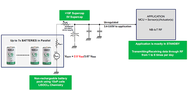
Figure 1: Typical non-rechargeable power system for IoT applications
The choice of chemistry of the battery pack is also very important. Lithium thionyl chloride based (Li-SOCl2) primary cells offer the best compromise between cost, size and required performance, especially with ultra-low self-discharge current. These battery packs are available in different sizes (AA, AAA etc.) and the selection of any specific formfactor depends on the lifetime requirements of the design.
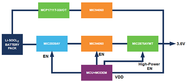
Figure 2: High level block diagram of the Microchip proposed solution
The Microchip optimized power scheme reference design has been developed to address the issues mentioned above. It supports different types of smart meters, from electricity and gas to water, that need to operate reliably across large areas. This drives the requirement for higher currents for longer range links, which often need a larger supercap. The proposed solution reduces the size of supercap by a factor of 20 in comparison to power schemes based on conventional linear regulator and supercap approach, allowing smaller battery packs that deliver a more efficient power scheme, a longer lifetime before replacement and higher reliability. This is achieved by using the supercap smartly during the transmission link phase of the communication link only while keeping it cutoff and discharged during the lower power intervals to avoid its leakage current power dissipation.
Other than smart metering this solution is also useful for other NB-IoT applications such as asset tracking, smart farming, smart cities waste management and parking along with smart buildings access control etc. The key to the reference design is the separate high power and low power paths, coupled with a programmable load switch. The power scheme is controlled by a 16-bit PIC16F1769 microcontroller that can switch from the low-power sleep mode to the high-power mode for data transmission. In lower power modes, the high-power path is disabled, and a low quiescent current power circuit based on the MCP1711 (Low dropout (LDO) regulator) and MIC94060 (High-side power switch) is activated. This helps to extend the life of the battery pack and the overall efficiency of the system. High-power path remained disconnected during this time to optimize the overall efficiency.
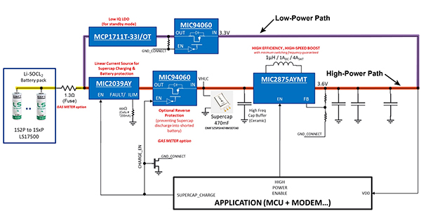
Figure 3: Low power and high-power paths in the Microchip proposed solution
As the current requirement increases from the NB IoT modem the high-power path is enabled. In this mode the power scheme employs a battery pack charging the supercap to a voltage close to its nominal voltage (around 3.6V). The supercap compensates for voltage drops and current source limitation of the battery pack. The design uses a low-cost controlled current source MIC2039 to charge the supercap right before the high power requirement of the NB IoT modem. MIC2039 acts as a linear current source to charge the supercap before the high current is pulled from it. This mechanism ensures overload protection to avoid the battery pack stress without exceeding its maximum pulse current specification. This controlled and predictable supercap charging process means that the charging just needs to be enabled before the application initiates tasks that need higher power.
Using this accurate current source to charge the supercap results in a deterministic charge time or charge recovery time that converges faster to the battery pack voltage than a Resistor-Capacitor (RC) charging solution. The MIC2039 also acts as a load switch by disconnecting the supercap from the battery pack when higher power is not required. MIC2039 feature an adjustable output current limit that is resistor programmable from 0.2A to 2.5A. The supercap in turn powers the MIC2875 synchronous boost converter that operates either in bypass or boost mode depending upon the charged voltage of the supercap. The boost converter regulates the output voltage of the high-power path. MIC2875 is a compact and highly efficient 2 MHz synchronous boost regulator with an internal 4.8A switch. It features a bidirectional load disconnect function which prevents any leakage current between the input and output when the device is disabled. The boost feature enables the design to work even when the battery is discharged below its nominal voltage. The voltage across supercap can vary from 2.5V up to 3.65V depending upon the charge state of the battery pack. To minimize switching artifacts in the audio band, the MIC2875 is designed to operate with a minimum switching frequency of 45 kHz. It also features an integrated anti-ringing switch to minimize EMI which is important for meter designs with wireless links. The microcontroller supervises these operations by maintaining timing and synchronization among different devices of high and low power paths.
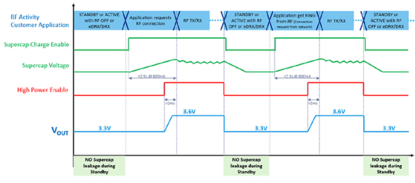
Figure 4: Timing and synchronization diagram of the Microchip proposed solution
The timing diagram indicates that during Standby (low power modes) the power supply provides 3.3V to the module. As the High Power Enable signal turns on, the power supply switches to high power mode and supplies output voltage of 3.6V. To prevent the supercap leakage current loss, it is required to ramp up the supercap voltage (for an appropriate time in advance, depending on battery pack size and supercap charge current settings) before the High Power Enable signal.
Reference Design BOM
| Part Number | Product Type | Description |
|---|---|---|
| PIC16F1769 | 16 bit PIC® Microcontroller | 14/20-pin, Up to 14KB, Up to 1K RAM, Op amps, ZCD |
| MIC2039 | Programmable 0.2A-2.5A High Accuracy High-Side Current Limit Power Switch | ADJ, High-Side, Power Distribution Switch |
| MIC94060 | High-side Load Switch 2A, 77mQ | Loadswitch w/level-shift |
| MCP1711 | 150 mA Ultra-Low lq, Capless LDO Regulator | 150 mA Ultra-Low Quiescent Current, Capless LDO Regulator |
| MIC2875 | 2MHz 4.8A Isw Synchronous Boost Regulator | Ultrasonic Synchronous Boost Regulator |
| MCP6444 | 450 nA, 9 kHz Op Amp | MCP6444 is a 9 kHz Op Amp with typical supply current of 450nA and operates from 1.4V to 6.0V. This quad Op Amp is available in SOIC and TSSOP packag |
| MCP6549 | Open-Drain Output Sub-Microamp Comparators | 600nA, 4us, Quad Channel Open-Drain Comparator |
Conclusion
Millions of smart meters are rolling out around the world to help tackle the climate crisis. Monitoring energy and water usage accurately and regularly helps to optimise the energy networks and improve efficiency. NB-IoT is key wireless technology for providing long distance, reliable links to smart meters. However, the challenges of placing smart meters in remote locations and providing reliable data links has led to the battery packs of NB-IoT modules being over specified, or reducing the battery life, leading to higher costs for both the system and the battery packs.
This validated non-rechargeable battery pack power scheme developed by Microchip combines a low cost 16bit microcontroller with a high-power path for charging a supercap for GSM back up link transmission and a low-power path for the sleep and listening modes. This enables a supercap that can be 20 times smaller than other designs, as well as a smaller battery pack that lasts longer to offer the best compromise between cost, size and performance.
This combination of optimized battery pack selection, controlled supercap charging and smart power management improves the reliability of the non-rechargeable battery pack-based NB IoT system. It also reduces the frequency of the battery pack replacement, cutting cost for equipment suppliers and maintenance operators.
Download article in PDF